Analog sensors are widely used in heavy industry, light industry, textile, agriculture, production and construction, daily life education and scientific research, and other fields. Analog sensor sends out a continuous signal, with voltage, current, resistance etc,the size of the measured parameters. For example, temperature sensor, gas sensor, pressure sensor and so on are common analog quantity sensor.
Analog quantity sensor will also encounter interference when transmitting signals, mainly due to the following factors:
1. Electrostatic induced interference
Electrostatic induction is due to the existence of parasitic capacitance between two branch circuits or components, so that the charge in one branch is transferred to another branch through the parasitic capacitance, sometimes also known as capacitive coupling.
2, Electromagnetic induction interference
When there is mutual inductance between two circuits, changes in the current in one circuit are coupled to the other through a magnetic field, a phenomenon known as electromagnetic induction. This situation is often encountered in the use of sensors, need to pay special attention to.
3, Leakage flu should interfere
Due to the poor insulation of the component bracket, terminal post, printed circuit board, internal dielectric or shell of capacitor inside the electronic circuit, especially the increase of humidity in the application environment of the sensor, the insulation resistance of the insulator decreases, and then the leakage current will increase, thus causing interference. The effect is particularly serious when the leakage current flows into the input stage of the measuring circuit.
4, Radio frequency interference interference
It is mainly the disturbance caused by the start and stop of large power equipment and the high-order harmonic interference.
5. Other interference factors
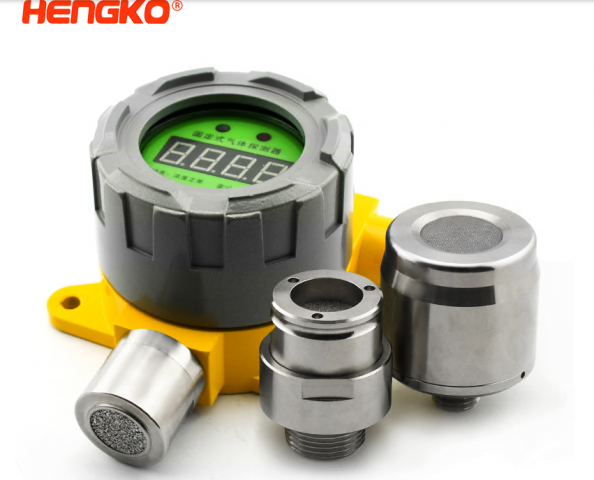
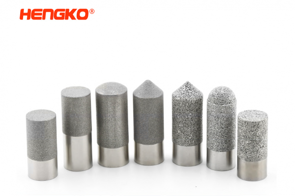
It mainly refers to the poor working environment of the system, such as sand, dust, high humidity, high temperature, chemical substances and other harsh environment. In the harsh environment, it will seriously affect the functions of the sensor, such as the probe is blocked by dust, dust and particulate matter, which will affect the accuracy of the measurement. In high humidity environment, water vapor is likely to enter the interior of the sensor and cause damage.
Choose a stainless steel probe housing, which is rugged, high temperature and corrosion resistant, and dust and water resistant to avoid internal damage to the sensor. Although the probe shell is waterproof, it will not affect the sensor response speed, and the gas flow and exchange speed is fast, so as to achieve the effect of fast response.
Through the above discussion, people know that there are many interference factors, but these are just a generalization, specific to a scene, may be the result of a variety of interference factors. But this does not affect our research on analog sensor anti-jamming technology.
Analog sensor anti-jamming technology mainly has the following:
6. Sheilding Technology
Containers are made of metal materials. The circuit which needs protection is wrapped in it, which can effectively prevent the interference of electric or magnetic field. This method is called shielding. Shielding can be divided into electrostatic shielding, electromagnetic shielding and low frequency magnetic shielding.
(1)Electrostatic Shieding
Take copper or aluminum and other conductive metals as materials, make a closed metal container, and connect with the ground wire, put the value of the circuit to be protected in R, so that the external interference electric field does not affect the internal circuit, and conversely, the electric field generated by the internal circuit will not affect the external circuit. This method is called electrostatic shielding.
(2)Electromagnetic Shielding
For the high frequency interference magnetic field, the principle of eddy current is used to make the high frequency interference electromagnetic field generate eddy current in the shielded metal, which consumes the energy of the interference magnetic field, and the eddy current magnetic field cancels the high frequency interference magnetic field, so that the protected circuit is protected from the influence of the high frequency electromagnetic field. This shielding method is called electromagnetic shielding.
(3) Low Frequency Magnetic Shielding
If it is a low-frequency magnetic field, the eddy current phenomenon is not obvious at this time, and the anti-interference effect is not very good only by using the above method. Therefore, high magnetic conductivity material must be used as the shielding layer, so as to limit the low-frequency interference magnetic induction line inside the magnetic shielding layer with small magnetic resistance. The protected circuit is protected from low frequency magnetic coupling interference. This shielding method is commonly referred to as low frequency magnetic shielding. The iron shell of the sensor detection instrument acts as a low frequency magnetic shield. If it is further grounded, it also plays the role of electrostatic shielding and electromagnetic shielding.
7. Grounding technology
It is one of the effective techniques to suppress interference and the important guarantee of shielding technology. Correct grounding can effectively suppress external interference, improve the reliability of the test system, and reduce the interference factors generated by the system itself. The purpose of grounding is twofold: safety and interference suppression. Therefore, grounding is divided into protective grounding, shielding grounding and signal grounding. For the purpose of safety, the casing and chassis of the sensor measuring device should be grounded. Signal ground is divided into analog signal ground and digital signal ground, analog signal is generally weak, so the ground requirements are higher; digital signal is generally strong, so the ground requirements can be lower. Different sensor detection conditions also have different requirements on the way to the ground, and the appropriate grounding method must be chosen. Common grounding methods include one-point grounding and multi-point grounding.
(1) One-point grounding
In low frequency circuits, it is generally recommended to use one point grounding, which has a radial grounding line and a bus grounding line. Radiological grounding means that each functional circuit in the circuit is directly connected with the zero potential reference point by wires. Busbar grounding means that high-quality conductors with a certain cross-sectional area are used as the grounding bus, which is directly connected to the zero potential point. The ground of each functional block in the circuit can be connected to the nearby bus. Sensors and measuring devices constitute a complete detection system, but they may be far apart.
(2) Multi-point grounding
High-frequency circuits are generally recommended to adopt multi-point grounding. High frequency, even a short period of ground will have larger impedance voltage drop, and the effect of distributed capacitance, impossible one-point earthing, therefore can be used flat type grounding method, namely the multipoint earthing way, using a good conductive to zero potential reference point on the plane body, the high frequency circuit to connect to the nearby conductive plane on the body. Because the high frequency impedance of the conductive plane body is very small, the same potential at each place is basically guaranteed, and the bypass capacitor is added to reduce the voltage drop. Therefore, this situation should adopt the multi-point grounding mode.
8. Filtering technology
Filter is one of the effective means to suppress AC serial mode interference. The common filter circuits in the sensor detection circuit include RC filter, AC power filter and true current power filter.
(1) RC filter: when the signal source is a sensor with slow signal change such as thermocouple and strain gage, the passive RC filter with small volume and low cost will have a better inhibition effect on series mode interference. It should be noted, however, that RC filters reduce series mode interference at the expense of system response speed.
(2) AC power filter: the power network absorbs a variety of high and low frequency noise, which is commonly used to suppress the noise mixed with the power supply LC filter.
(3) DC power filter: DC power supply is often shared by several circuits. In order to avoid the interference caused by several circuits through the internal resistance of the power supply, RC or LC decoupling filter should be added to the DC power supply of each circuit to filter out low-frequency noise.
9. Photoelectric coupling technology
The main advantage of photoelectric coupling is that it can effectively restrain the peak pulse and all kinds of noise interference, so that the signal-to-noise ratio in the signal transmission process is greatly improved. Interference noise, although there is a large voltage range, but the energy is very small, can only form a weak current, and the photoelectric coupler input part of light emitting diode is work under current condition, general guide electric current of 10 ma ~ 15 ma, so even if there is a big range of interference, the interference will be unable to provide enough current and suppressed.
See here, people believe people have a certain understanding of the analog sensor interference factors and anti-interference methods, when using the analog sensor, if the occurrence of interference, according to the above content one by one investigation, according to the actual situation to take measures, must not blind processing, to avoid damage to the sensor.
Media Contact
Company Name: HENGKO
Contact Person: Media Relations
Email: Send Email
Phone: 0086-755-88823250
Country: China
Website: https://www.hengko.com/